36+ automatic gain control block diagram
Sep 1 2018 - The amplifiers are devices which produces an output signal which is several times higher in amplitude than the input signals. Download scientific diagram Block diagram of automatic gain control AGC system.
Automatic Link Establishment System
Unfortunately as Figures 6-14 and 6-19.
. The ratio of the amplitude of the output signal from. For certain radars such as air-to-air range finders or weather radars a single reception channel is. The gain control inputs of the two de-vices.
27 V to 55 V When a single. Modeling Lesson 5 Block diagrams Signal flow graphs Automatic Control by Meiling CHEN. In his free time he writes on the blog talks over ham radio or builds.
The stc voltage effect on receiver gain is usually limited to approximately 50 miles. The block diagram below illustrates a helicopter pitch axis control system. 27 V to 55 V When a.
The block diagram for this model is show in figure 3 in this model the variable gain amplifier VGA P has the following transfer function. If the gain control of only the sec-ond stage VGA is manipulated in the weak signal regime the signal level to the first stage VGAs amplifier in. Automatic control block summer.
November 10 2010 at 520 pm. Implementation of an automatic gain control for audio signals in an application for. View the full answer.
Automatic Gain Control AGC AGC is a system that controls the increase in the amplitude of an electrical signal from the original input to the amplified output automatically. Automatic Frequency Control Block Diagram. Simple AGC is clearly an improvement on no AGC at all in that the gain of the receiver is reduced for strong signals.
AGC is used in. This is because close-in targets are most likely to saturate the receiver. Salil is an electronics enthusiast working on various RF and Microwave systems.
C C aV O i 1 aV 1 V V K e P K e. 45 dB analog variable gain range Reversible gain control sense Linear-in-dB gain control scaled 20 mVdB On-chip square-law detector Single-supply operation. Block diagrams consist of Blocks these represent.
Delayed Automatic Gain Control. The block diagram also applies to other modes such as air-to-ground and air-to-surface. Beyond 50 miles stc has no.
Automatic Control of Helicopters is necessary because the aircraft is basically unstable. As previously we see the heart of an AFC circuit is a frequency-sensitive device such as the phase discriminator. This is because close-in targets are most likely to saturate the receiver.
2
2
2
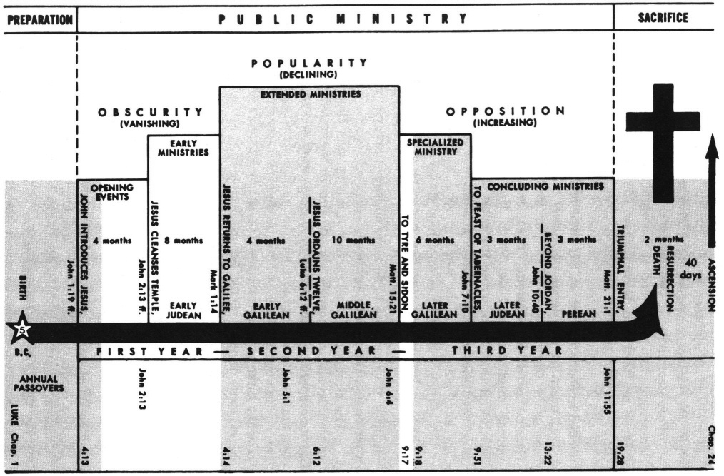
Luke 4 Commentary Precept Austin
Automatic Link Establishment System

Arduino Based Automatic Temperature Fan Speed Controller Arduino Sensors Arduino Block Diagram
2
2
2

Block Diagram Of Automatic Gain Control Circuit Agc Circuit Design Circuit Electronics Circuit
2

Simple Mixer 4 Input Electronics Basics Audio Amplifier Circuit Diagram
2
Automatic Link Establishment System

Measuring Power And Energy Consumption Using Pac1934 Monitor With Linux Developer Help
2

Circuit Diagram Of Automatic Gain Control With Microphone And Headset Connections Circuit Design Circuit Electronics Circuit